

Electrical connections
Questi contenuti non sono ancora disponibili nella tua lingua.
System overview
Section titled “System overview”modual delivers the modual Core, the HV battery system and the HV inverter, pre-wired to each other. The customer provides the connections at the bottom of the table.
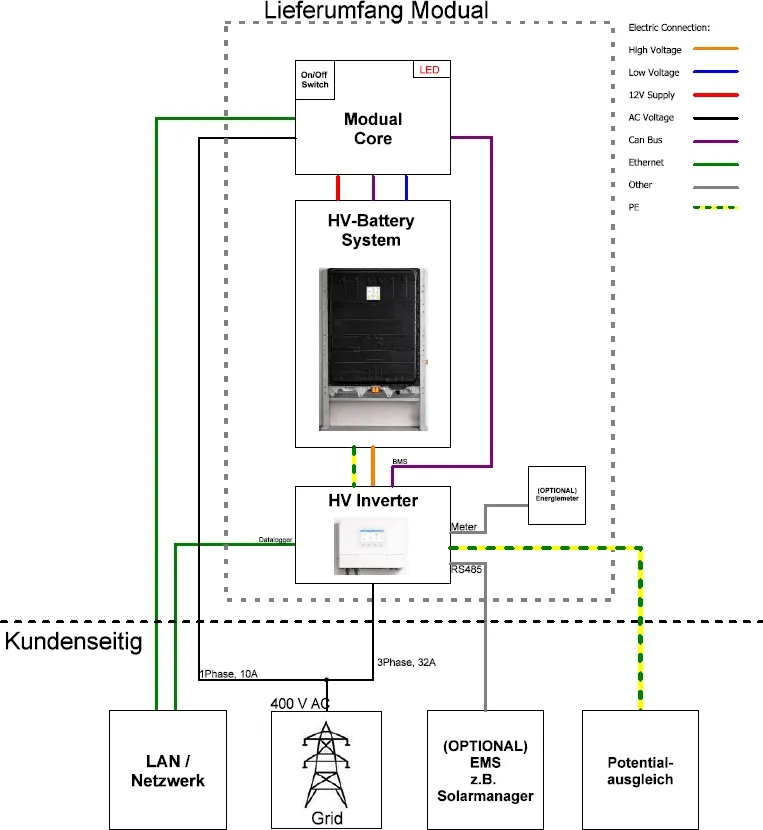
| Connection | From | To | Type |
|---|---|---|---|
| Power supply (12 V), low voltage, CAN bus | modual Core | HV battery | Pre-wired |
| High voltage DC and PE | HV battery | HV inverter | HV connector, earth cable |
| BMS data | modual Core | Inverter “BMS” port | CAN bus |
| Energy meter (optional) | Inverter “Meter” port | Eastron energy meter | RS485 |
| Mains supply | Customer | modual Core | 230 V, 1-phase, 10 A |
| Network | Customer LAN | modual Core | Ethernet |
| Network | Customer LAN | Inverter data logger | Ethernet or Wi-Fi |
| Grid | Customer | Inverter “GRID” terminal | 400 V AC, 3-phase, 32 A |
| EMS (optional) | e.g. Solar Manager | Inverter “RS485” port | RS485 |
| Equipotential bonding | Building | Inverter | PE |
Rack overview
Section titled “Rack overview”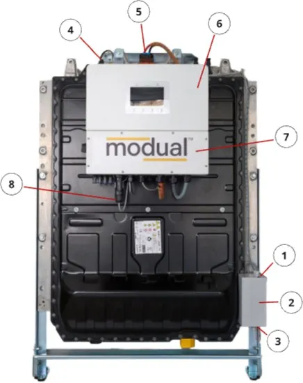
| No. | Component |
|---|---|
| 1 | Battery status LED |
| 2 | modual Core |
| 3 | Network connection, main switch, mains connection (underside of the modual Core) |
| 4 | Battery signal connector |
| 5 | HV battery connector |
| 6 | Battery inverter |
| 7 | Inverter network connection |
Connecting the system
Section titled “Connecting the system”-
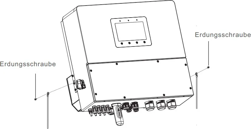
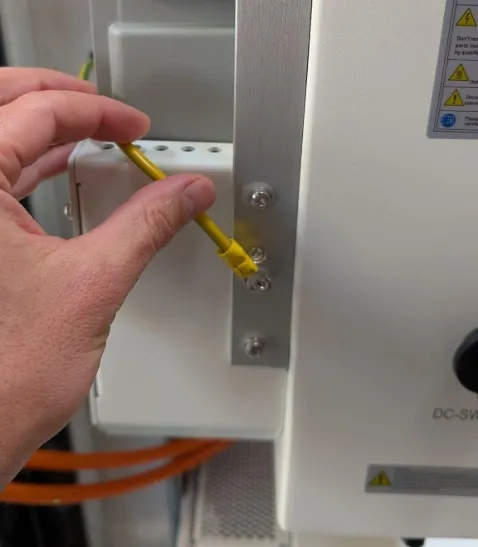
Connect the earth terminal of the battery pack to the inverter, using the earthing screw on the inverter. With the inverter mounted on the pack, this connection is already in place.
-
Connect the inverter to the building’s equipotential bonding system.
-
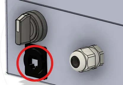
Connect the modual Core to the local network, using the RJ45 socket on the underside of the housing.
-
Connect the Solis inverter to the local network, through the network interface of the Solis data logger or through the local Wi-Fi. See the Solis inverter user manual.
-
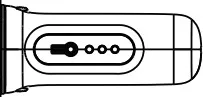
Remove the cover of the Solis inverter (8 screws). Connect the data cable from the modual Core to the BMS port of the inverter. With the inverter mounted on the pack, this connection is already in place.

-
If you are using a compatible energy management system (e.g. Solar Manager Connect 2), connect its RS485 cable to the RS485 port of the inverter.

-
If you are using the supplied energy meter (Eastron), connect it to the Meter port of the inverter. The pin assignment is the same as for RS485 above.

-
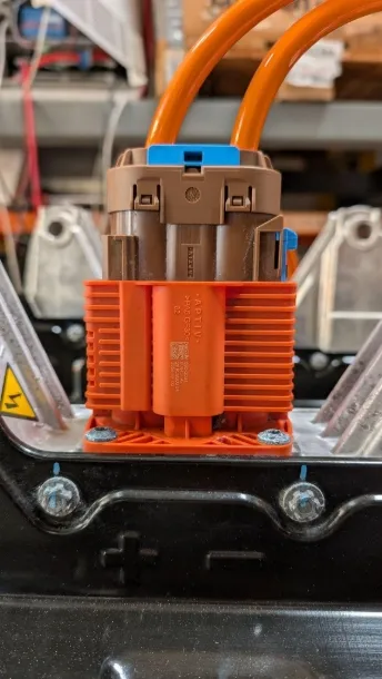
Carefully plug the prepared HV connector into the battery pack. You should hear and feel it click into place.
-
Connect the power cable of the modual Core to a T13 socket (230 V / 50 Hz). If your installation requires it, you can instead connect the cable directly to an additional junction box. The circuit must be fused at 10 A.
-
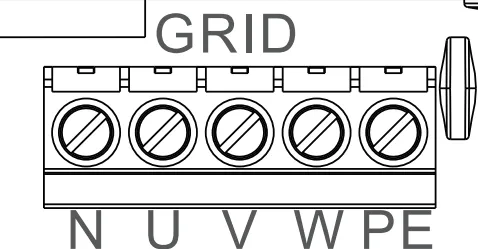
Connect the 3-phase AC cable to the GRID terminal of the inverter (N, U, V, W, PE).
-
Carry out all measurements required by law.
-
Refit the cover of the Solis inverter with the 8 screws.
Continue with commissioning.