

Electrical connections
System overview
Section titled “System overview”The Pro 70 consists of one modual Core, two HV battery systems (70-1 and 70-2) and two HV inverters, the master (70-1) and the slave (70-2). modual delivers these components; the customer provides the connections marked “Customer”.
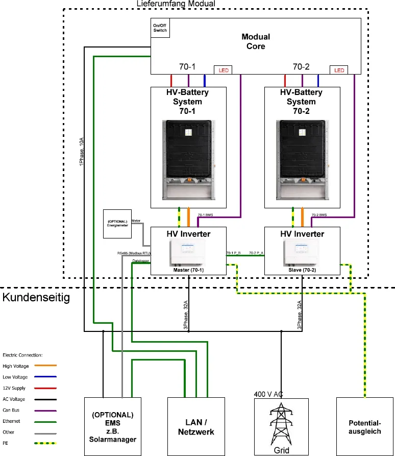
| Connection | From | To | Type |
|---|---|---|---|
| Power supply (12 V), low voltage, CAN bus | modual Core | HV battery 70-1 and 70-2 | Pre-wired |
| High voltage DC and PE | HV battery 70-1 / 70-2 | Master / slave inverter | HV connector, earth cable |
| BMS data | modual Core (cables 70-1, 70-2) | “BMS” port of master / slave | CAN bus |
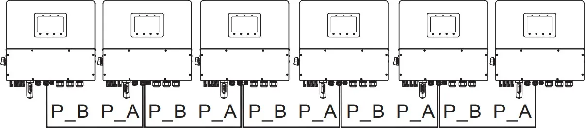
| Parallel link | Master “PAR-B” | Slave “PAR-A” | Network cable |
| Energy meter (optional) | Master “Meter” port | Eastron energy meter | RS485 |
| EMS (optional) | e.g. Solar Manager | Master “RS485” port | RS485 (Modbus RTU) |
| Mains supply | Customer | modual Core | 230 V, 1-phase, 10 A |
| Network | Customer LAN | modual Core | Ethernet |
| Network | Customer LAN | Master data logger | Ethernet or Wi-Fi |
| Grid | Customer | “GRID” terminal of each inverter | 400 V AC, 3-phase, 32 A each |
| Equipotential bonding | Building | Both inverters | PE |
Connecting the system
Section titled “Connecting the system”-
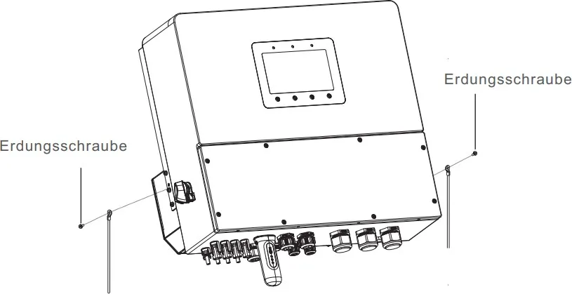
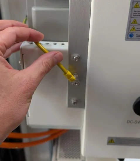
Connect the earth terminal of each battery pack to its inverter, using the earthing screw on the inverter.
-
Connect both inverters to the building’s equipotential bonding system.
-
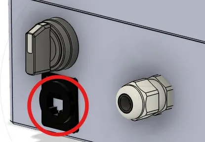
Connect the modual Core to the local network, using the RJ45 socket on the underside of the housing.
-
Remove the covers of both Solis inverters (8 screws each). Then connect:
- the modual Core data cable labelled 70-1 to the BMS port of the master (70-1);
- the modual Core data cable labelled 70-2 to the BMS port of the slave (70-2).

-
Connect the master inverter (70-1) to the local network, through the network interface of the Solis data logger or through the local Wi-Fi. See the Solis inverter user manual.
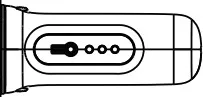
-
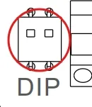
Connect the two inverters with an additional network cable: from the PAR-B port of the master to the PAR-A port of the slave. Check that the DIP switches on both inverters are set to ON.
-
If your energy management system (e.g. Solar Manager Connect 2) requires Modbus RTU control, connect its RS485 cable to the RS485 port of the master (70-1).

-
If you are using the supplied energy meter (Eastron), connect it to the Meter port of the master inverter. The pin assignment is the same as for RS485 above.

-
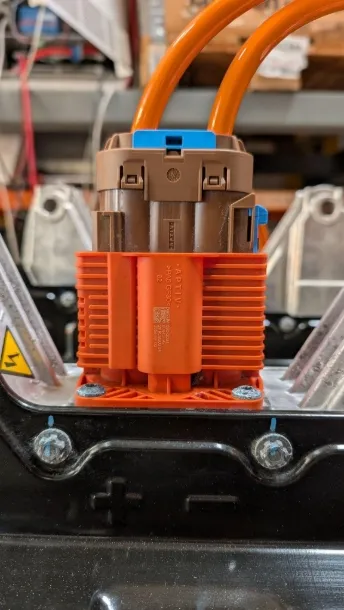
Carefully plug each prepared HV connector into its battery pack. You should hear and feel it click into place.
-
Connect the power cable of the modual Core to a 230 V / 50 Hz socket. If your installation requires it, you can instead connect the cable directly to an additional junction box. The circuit should be fused at 10 A.
-
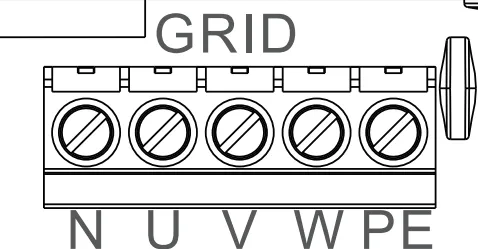
Connect a 3-phase AC cable to the GRID terminal of the master inverter (N, U, V, W, PE). Repeat with the second AC cable on the slave inverter.
-
Carry out all measurements required by law.
-
Refit the covers of both Solis inverters with their 8 screws.
Continue with commissioning.